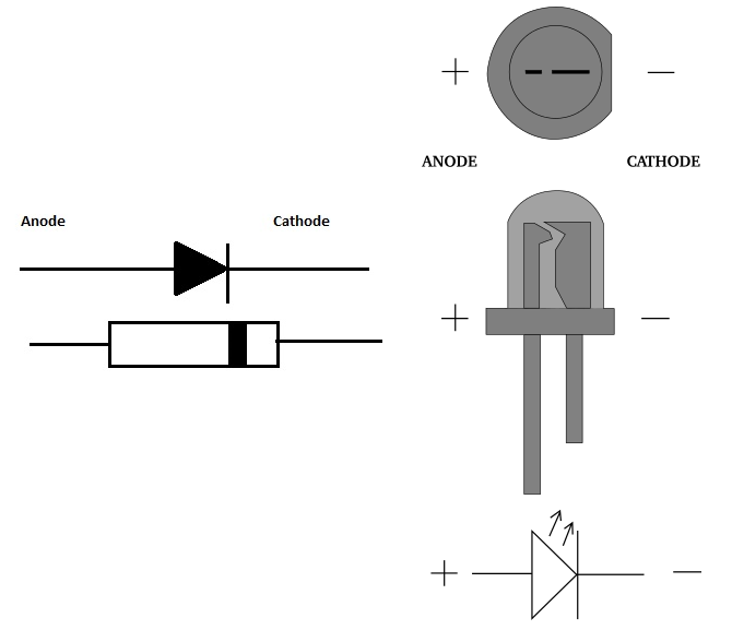
In order to demonstrate the working principle of the diodes, let us experiment with them. The idea is to connect the diode and the LED in series in order to prove that the diode conducts in only one direction. But first, we must discover the proper way of orienting the diode and the LED in the circuit, which is self-explanatory from the following figure.
(Sources: referenced)
Hence, in the following experiment, we will show how the orientation of the diode can complete or break the circuit which will be manifested by the LED.
Components:
- breadboard
- 5V power supply
- 3mm red LED
- 1N4007 rectifier diode
- 150Ω resistor

During the practical realization of experiments, it is important to acquire comfort in the sense that the realized circuit does not have to fully correspond to the schematic in terms of orientation and arrangement of components. Often this is not even possible, so it is very important to get used to this fact immediately. Here, we were quite lucky, though.

Explanation: From the previous figure, it is obvious that the LED is lit only if we connect the diode in forward bias direction, which completes the circuit. That means that changing the orientation of the diode (or the LED) would break the circuit and the current would not flow. What is less obvious is the reasoning behind the selection of the components, and why the diode does not glow very bright. In order to figure that out, we must dive a little deeper into the circuit and explain some basic phenomena.
First of all, let us see how much voltage we need to forward bias both the LED and 1N007 diode. If we check out the specification of the red LED diode, we can find out that the typical forward voltage drop is from 1.7 to 2V (we can use the value 1.8V for simplicity of the calculations), and the maximum rated forward current is 20mA. Further, 1N4007 diode is a silicon diode so we can expect it to have a forward voltage drop of ~0.7V. In its datasheet, it also mentioned that the maximum forward current the diode can stand is 1A. Since we need a maximum of 20mA to glow the LED, we are on the safe side here. So, at the moment we have a couple of important informations:
- we need to provide ~2.5V for both the LED (~1.8V) and the diode 1N4007 (~0.7V)
- we need a maximum of 20mA of current for the red LED. Since we are connecting all components in series, the current has only one path and, as a consequence, the current value will be equal in all parts of the circuit
- we have a power supply of 5V, which is excessive voltage
So, we must find a way to lower the voltage from 5V to ~2.5V, not to burn the LED with excessive current. For that purpose, we use a resistor – an electrical component whose primary function is to limit the flow of electric current by producing the voltage drop across its terminals.
According to Ohm’s law, the current (I) through the component, in this case, the resistor, is proportional to the voltage (V) across it, and inversely proportional to its resistance (R), as noted in the following formula:

From this formula, it is very easy to find the resistor value, because we have to cause a ~2.5V drop on it, and we know the current needed is 20mA:

Since resistors introduce certain tolerances (the true resistance can be more or less the noted value), we used a 150Ω resistor because we wanted to be conservative enough not to burn the LED. Further, the voltage drop on the resistor dissipates electrical power which is converted into heat, so we need to take into consideration also the resistor power rating to prevent it from burning up. For that purpose we use the following formula to calculate the electrical power (P):
P = I * V
Rearranging it according to Ohm’s law, we can easily get to the following expression, that is more suitable:
P = I * I * R = I2 * R
And if we supply our values, we get to the required power rating:
P = (0.02A)2 * 150Ω = 0.06W
Since power rating standards for resistors are 0.125W, 0.25W, 0.5W, 1W, and higher, we are perfectly safe whichever one we choose.
Finally, after the experiment, we can use a multimeter to measure the voltage drops for the different components in the circuit, and current through it, to see whether our calculations and assumptions were correct. My readings are the following:
- Voltage drops:
- 1N007 diode: ~0.71V (correct assumption)
- red LED: ~2.1V (wrong assumption, acceptable)
- resistor ~2.1V (wrong calculation)
- Current: ~15mA (less than desired)
Since the current measured in the circuit is only 15mA, it is logical that the LED does not glow as bright as it would for 20mA. In other words, we were too conservative, and we could have freely used a 100Ω resistor without causing any problems.
References:
